TTEC 4826 - Engine Electronic Control Systems (Off - Car)/(On - Car)
Off-Car Practical Lesson Book
Sensors
-Throttle Position Sensor (TPS)
The TPS that I used in this experiment is a, Toyota 89452 - 22090 Denso.
The internal workings of this TPS is as follows, As the accelerator pedal is pushed the throttle plate opens, rotating the sensors internal variable resistor. As the throttle opens, voltage returned to the computer from the throttle position sensor varies, (normally increasing), signalling the rate of throttle opening as well as throttle position. The computer uses this information to adjust fuel trim, which is the amount of time the injectors are open, delivering more fuel.
The TPS will now be connected to a 5V power supply so that the voltage output can be tested at different voltages.
Throttle Angle (°C) Voltage Output (V)
0 0.549
10 1
22.5 2.08
45 2.40
67.5 3.31
90 3.92

Throttle Position Switch (TPS)

If the Throttle Position Switch seems to be a possibility for your vehicle not running correctly then the condition of the contacts inside the switch is the first test, and should be checked for high resistance in both idle and full throttle position. To do this on a 3 pin TPS, place your earth ohmmeter lead onto the earth pin of the TPS and your positive lead onto either the IDL (Idle Circuit) pin, followed by the PSW (Power Switch), also known as WOT (Wide Open Throttle), whilst keeping your earth lead on the E (Earth) pin.
My results at both PSW and IDL pins were 0.6Ω showing continuity. This result is what you would expect to find on a working TPS.
At PSW -WOT= 0Ω At IDLE - Idle= 0Ω
-Idle= OL - WOT= OL
The results above indicate to me that at Idle, Idle is 0Ω and at PSW, WOT is 0Ω resulting in 0Ω meaning on and OL meaning off.
The Throttle Position Switch is operated by the throttle. In early L-Jetronic systems the TPS has a set of contacts for idle and full throttle positions. When checking the TPS with an ohmmeter, readings of 0.6Ω or close to it shows continuity at each point. The resistance between idle and WOT varies depending on the car, the switch then signals the throttle opening to the ECU which then provides mixture corrections for both idle, off-idle and full throttle conditions.
MAP) & (IAT) Sensors off car
Wire up a map sensor with a 5v feed and earth . Meassure the return voltage from the third wire.
Using a mity-vac apply vacuum to the map sensor. Plot the voltage return in relation to the vacuum applied.


Dose the map sensor match the manufactures specifications, why or why not?
The plotted graph line was very similar but slightly different because I used a different map sensor.
Dose the map sensor read a vacuum or preasure?
The map sensor has a silicon chip that changers its resistance depending on the changers of pressure.
Explain the internal operation of this sensor and why the output voltage changes.
The map sensor has vacuum chamber which is connected to the intake manifold. Inside the vacuum chamber is a silicon chip that has a reference pressure on one side. On the other side it meassures changes in the intake manifold pressure by changing its resistance depending on changes of pressure. This changing resistance varies the voltage signal to the ECU which then interprets changing voltage as engine load and calculates how much fuel to inject and when to ignite
Air Flow Meter- off car

An air flow meter operates similar to an TPS. It has a potentiometer inside it and the swivel arm that attachs to the signal is hooked up to the flap piece that opens and closes. As the flap moves it moves the arm up and down the potentiometer (variable resistor) changing the output voltage depending on where it is on the potentiometer. The signal is sent to the ECU and tell it how much air flow is in the intake manifold

Vane or Flap Air Flow Sensor/Meter (AFM)
Checking sensor operation.
Vane type air flow meters:

Table for the vane angle and voltage out

Plot your results on thr graph

Are your results within the manufacturer's specifications, why or why not?
It is not because my graph does not look right.
Explain its internal operation and why your voltage changes.
The vane moves and allows the air flow into the engine. The vane is connected to the potentiometer which has variable resistor
Engine Coolant Temperature or ECT sensor
ECT sensor is a very important for engine cold start and an open loop running of the engine. Its a negative temperature coefficient, which means the colder the sensor the more resistance it produce, the hotter the temperature the less resistance. This sensor determine injectors cold start duty cycle

Plot the restance and temperature on the graph below.
Temperatue
Measure the risstance between the teminal.
Water Temperature | Resistance |
19 d c | 2.66 K ohms |
30 d c | 1.09 K ohms |
35 d c | 1.22 K ohms |
40 d c | 1.22 K ohms |
50 d c | 0.88 K ohms |
66 d c | 0.65 K ohms |
70 d c | 0.57 K ohms |
80 d c | 421 .1 ohms |
90 d c | 352 ohms |
Thermo fan switch


20Degrees=0.7K ohms
30 Degrees=0.692K ohms
40 Degrees =0.580K ohms
50 Degrees=0.46K ohms
60 Degrees=0.35K ohms
70 Degrees=0.28K ohms
80 Degrees=0.22K ohms.
I am unsure if it meets manufacturers specifications because i dont know what car this thermo fan switch is off. A thermistor is a type of resistor whose resistance changes greatly with temperature. The above reading show that this is a thermistor. The resistance changes because that is how a thermistor operates. It works by turning the fan on when X amount of ohms is reached i am unsure of the exact number in this situation. This is a NTC thermistor. (Negative temperature coefficient
Testing Ignition Coils (off car)
.jpg)
Test primary windings for IC-13 coil = 0.6Ω

Test secondary windings = 6.48KΩ

.jpg)
Wasted spark coil pack secondary windings :
Coil 1 = 7.09KΩ

Test secondary windings = 6.48KΩ

.jpg)
Coil 1 = 7.09KΩ


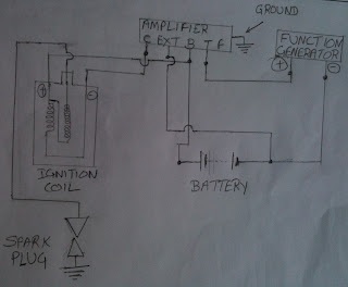
Wire up an ignition amplifier using a function generator to trigger the module.
Have a coil and spark plug in the circuit so the spark plug can fire
Wiring up ignition systems
Wire up an ignition module using a function generator to trigger the module.
Have a coil and spark plug in the circuit so the spark plug can fire
Draw a wiring diagram of how you wired the circuit

Draw a wiring diagram of how you wired the circuit


Q. Find the maximum current value of the transistors from the data sheet, the resistancne of the coil. Then calculate the resistor need to protect the circuit. Show calculations.


Calculation for B1 resistance:
Base current at B1(Ib) = 1A
Supply voltage = 5 V
Voltage drop Vbe = 0.7 V
Voltage at base Vb = 5-0.7 = 4.3 V
V=IR
R= 4.3/1 = 4.3 ohm
Calculation for R3:
V = 12 V
Ic = 3 A
V= IR
Resistance of ignition coil is 1.2 ohm
V = I(1.2 + R3)
(1.2 + R3) = 12/3=4
R3 = 4-1.2= 2.8 ohm
So R3 = 2.8 ohm
Instead of the calculated values of R and R3, we used in our experiment 4.7 ohm and 3.3 ohm resistance respectively as available in the Lab.
Q. What difficulties did you encounter in building this circuit?
A. At beginning, we faced difficulty in finding resistance R and R3 but we struggled with and finally we found those.
Q. If you were going to build this circuit again what would you do differently?
A. we would try to find the resistance instantly
Intake Air Temperature Sensor (IAT)
Have a coil and spark plug in the circuit so the spark plug can fire
Draw a wiring diagram of how you wired the circuit


Wire up an ignition module using a distributor to trigger the module
Have a coil and spark plug in the circuit so the spark plug can fireDraw a wiring diagram of how you wired the circuit

Wire up the wasted spark ignition system using the function generator to trigger the modules.
Have the coils and sparks plug in the circuit so the spark plugs can fire.
Draw a wiring diagram of how you wired the circuit


Wire up the coil over ignition system using the function generator to trigger the module
Have the coil and spark plug in the circuit so the spark plug can fire
Draw a wiring diagram of how wired the circuit.Have the coil and spark plug in the circuit so the spark plug can fire


Building a simplified ignition module
Build the ignition circuit below on a breadboard using two 2N2222 transistorsQ. Find the maximum current value of the transistors from the data sheet, the resistancne of the coil. Then calculate the resistor need to protect the circuit. Show calculations.


Calculation for B1 resistance:
Base current at B1(Ib) = 1A
Supply voltage = 5 V
Voltage drop Vbe = 0.7 V
Voltage at base Vb = 5-0.7 = 4.3 V
V=IR
R= 4.3/1 = 4.3 ohm
Calculation for R3:
V = 12 V
Ic = 3 A
V= IR
Resistance of ignition coil is 1.2 ohm
V = I(1.2 + R3)
(1.2 + R3) = 12/3=4
R3 = 4-1.2= 2.8 ohm
So R3 = 2.8 ohm
Instead of the calculated values of R and R3, we used in our experiment 4.7 ohm and 3.3 ohm resistance respectively as available in the Lab.
Q. What difficulties did you encounter in building this circuit?
A. At beginning, we faced difficulty in finding resistance R and R3 but we struggled with and finally we found those.
Q. If you were going to build this circuit again what would you do differently?
A. we would try to find the resistance instantly
Intake Air Temperature Sensor (IAT)
Temperature (°C) Resistance (Ω)
20 2700
40 1890
50 932
70 466
80 356
95 214

Temperature increases and resistance decreases, this sensor is working right.
The IAT sensor is a negative temperature co-efficient thermistor.
My results from the air temperature sensor and the engine coolant temperature sensor tells me that these sensors are both negative temperature co-efficient thermistors. This is shown by the same experiment being tested upon both sensors. As the temperature increases, resistance decreases. This information is sent again to the PCM through means of a 5V reference wire. The resistance in the sensor is high when cold but drops as the sensor warms up to alter the return voltage signal back to the PCM. The PCM uses this changing voltage to determine the engine temperature.
Knock Sensor
An oxygen sensor is used by a vehicle to determine how much oxygen there is within the exhaust gasses. The amount of oxygen present allows the ECU to determine the correct amount of fuel to inject to achieve a stoichiometric fuel burn.
This picture gives a good view of the internal operation of an oxygen sensor:

Oxygen sensors operate at very high temperatures and because of this, they are effective only when the engine is running at operating temperature. Many modern oxygen sensors include a heating element to allow faster switching to closed loop operation of the ECU.

To test the oxygen sensors, we used a gas torch and a voltmeter. When heated, oxygen sensors produce a voltage up to about .9V. Heating the O2 sensor up with a gas torch will allow us to find any faults with the sensor and gauge how quickly it will react.
When the flame was applied to the sensor, we saw an increase in voltage to about 0.5V, as the heat is removed, the voltage drops to approximately 0.1V. As heat is held onto the sensor for a longer period, the voltage increases even more. In our test, it rose to approximately .85V.
This graph shows the relation between air fuel ratio's and oxygen sensor voltages:


This waveform was not recorded in-class. It was taken off google images because the oscilloscope used in-class was not able to capture a waveform due to the small voltage it put out and the oscilloscope's voltage per division not being able to go low enough.
The knock sensor is designed to allow the engine to run at the most advanced timing possible without detonating. As soon as detonation, or pinking, occurs the knock sensor sends a voltage to the ECU, telling it to retard the timing in order to stop detonation from occurring, the timing is then slowly advanced constantly until detonation happens again and the knock sensor does its thing. This system allows the car to run at optimum efficiency. The voltage you see from the knock sensor without any voltage being supplied to it is from the knock sensor having peizo-electric crystals
Check Air Gap :
Using a feeler gauge , meassure the air gap between the pickup coil protection and the reluctor tip.
.jpg)

Capture the signal waveform on a digital oscilloscope and record below show peak to peak voltages as well as wave time.

Describe the waveform what is happening at different points.
When we spin the reluctor a pole pice on the wheel approaches the trigger assebbly until the air gap is at is smallest now the pick up coil has reached saturation a positive voltage is induced you can see this as point A on photo. As the reluctor wheel moves away the magnetic field collapses causing a inducied voltage in the opposite direction you can see this at point B
Hall Effect Sensors :
Wire up a distributor and connect an oscilloscope then spin the distributor and observe the wave form

In the photo above point (A) is the dwell time when the voltage is high and the blade is in the air gap and coil is grounded by the Hall intergrated IC. When a window moves into the air gap the magnetic field is able to cross to the hall IC pulling the voltage down to 0 this can be seen a point (B) and (C). This is the firing point
Optical Distributor
On the waveform above, you can see that the Optical Distributor begins on. Next one of the four blades on the (Chopper Plate) will interrupt the signal in the photo electric shell, switching it off. This switching happens faster as the car is under higher load driving conditions.
In all of the speed sensors above , the degrees turned of the distributor is always half the speed of the crankshaft. For example, a 360° (1 rotation) of the distributor will result in a 720° or 2 rotations of the crankshaft.
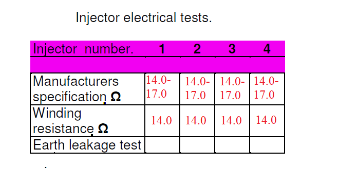
Injector Testing

This is checking the resistance of the injectors with using the multi meter
To check the injectors for click. we wire up the injectors to power supply (12V)and listen to see if they click.


Faulty HL lead and spark plug may cause the injector is not firing.
Tes bench cleaning

When removing fuel injectors fom the engine make sure the pressure in the fule line is release, be careful of injector niddle.
Injector leakage: 0 drips per minute
Injector flow rate: 144cc per minute flow rate
Test result

How many injector requite attention? 0
All of the injectors deliver fuel in even cone shape pattern and there is no leakage (dribble) on all the injector when we apply full pressure and the injector is in close position. The rate of fuel deliver is 2.4ml per second.
Over all reasonably good however there is a number of things that i am unhappy with.
ReplyDelete1:your TPS is copied from another student. THIS IS NOT ACCEPTABLE!
2:Some of your graphs that you were meant to draw clearly are just copied and pasted
ANY WORK THAT IS NOT YOURS MUST BE REFERENCED!